Printing and plotting has changed drastically since the days of release 14 - there is much more flexibility. Unfortunately, flexibility sometimes adds complexity.
To plot successfully in AutoCAD, you have to familiarize yourself with the three main plotting tasks:
- Plotter Configuration (PC3 files)
- Pen Style Configuration (CTB and STB files)
- Page Setup
While these are the most important concepts to learn, it is also a good idea to become familiar with modelspace vs. paperspace, sheet layouts, and lineweights.
Plotter Configuration
In R14, configuring a plotter was fairly simple. You would execute the Preferences command from the Tools pull-down menu, click on the Printer tab, click on the New… button, and follow the instructions.
In subsequent releases, the procedures have changed. To begin, click on your Windows Start button -> Control Panel, you will notice the Autodesk Plotter Manager in the list. Double-click on the Autodesk Plotter Manager. This is where a plotter is configured for use in AutoCAD.
To configure a new plotter, double-click the Add-A-Plotter Wizard. Click Next> through the introduction page:
What should you choose? My Computer, Network Plotter Server, or System Printer? The answer depends on several things: Are you connecting to the plotter through the network or is it connected to your computer? What is the brand and model of the plotter? Are there Windows drivers for the plotter? Are there Autodesk Heidi drivers for the plotter?
Basically, My Computer and Network Plotter Server use Autodesk Heidi drivers and the System Printer uses Windows drivers. For 99% of printers, they are configured in your Windows system printers, so you will choose System Printer. Therefore, even if the plotter is directly attached to your computer or on the network, you will still choose System Printer. Only older HP plotters and non-HP plotters still use Autodesk Heidi drivers.
To find out if your plotter is configured in Windows, click on the Start button -> Control Panel -> Printers and check to see that it is in the list of printers. If it is not, and you do not have an Autodesk Heidi driver available for the printer, you must go through the Add-A-Printer Wizard to configure it in Windows first. You can download the latest drivers for your HP printer from HP's web site.
Continuing with the printer setup, we’ll choose a system printer for our HP DesignJet 1050C. Click Next>:
A list of printers configured in Windows is shown in the dialog box. The HP DesignJet 1050C has already been added as a system printer in Windows, and is being shared off of a computer named "dbserver." We’ll choose \\DBSERVER\HP DesignJet 1050C by HP and click Next>:
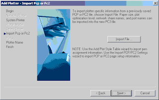
If you used PCP or PC2 files in AutoCAD R14, and would like to continue using them in newer versions of AutoCAD, you can’t. But you can import certain information from them into this printer setup. This information includes just about everything except color vs. line weight information. The color vs. lineweight info is taken care of later in Pen Style Configuration. Click Next>:
It’s a good idea to read all of the information contained in the dialog boxes as they come along. Here you simply name the printer. If the printer name/path is greater than 31 characters, you'll get an error message stating the that the ability to customize the printer will be limited because the name is too long. If possible, reduce the length of the printer name in Windows on the computer from which it is shared, in order to allow full customization capabilities (you will have to re-add the printer to other computers in the office once the name is changed). Click Next> and then click Finish. A printer configuration (PC3) file will now exist in the Autodesk Plotter Manager. When you execute the Plot or Page Setup command, this PC3 file should be in the list of plot devices. It is recommended to always use a PC3 file when plotting (HP DesignJet 1050C by HP.pc3), rather than the system printer (\\DBSERVER\HP DesignJet 1050C by HP) so that changes made to the properties of the plotter are saved to the PC3 file. If you try to customize the system printer, you'll end up making the same changes over and over again, as changes to the system printer cannot be saved. In 2005 products you have the option to hide system printers under the Tools->Options->Plot and Publish tab.
Pen Style Configuration
Different line widths and grayscales help bring life to a plotted AutoCAD drawing, providing a sense of meaning and style. This is best achieved through the use of plot style tables. Plot style tables are simple spreadsheet like tables where we can associate an AutoCAD color or layer to a pen width and grayscale amongst other things.
If you click on your Windows Start button, go to Settings, and Control Panel, you will notice the Autodesk Plot Style Manager in the list. Double-click on the Autodesk Plot Style Manager to bring up the list of available plot style tables. You may notice that some of the tables have CTB extension whereas others have an STB extension. CTB tables are "color-dependent plot styles" whereas STB tables are "Named Plot Styles." CTB tables are organized with colors associated to pen widths, grayscales, etc. STB tables are much more involved. With STB tables, you can create plot styles that can then be associated to layers. If you want to keep life simple for yourself, use CTB tables! STB tables are very powerful, and we may transition to them as time moves on. For more information on plot styles, see our web page on Color vs. Named Plot Styles.
Double-click on acad.ctb and click on the Form View tab:
Off to the left is where you choose the color that you want to configure, and off to the right is where you choose the plotting properties for that color. For example, if you want color 4 (cyan) to plot black with a 0.010" lineweight, you would set the color property to black and the lineweight property to 0.010" or 0.254 mm. If 0.010" is not an option under lineweights, you can click on the Edit Lineweights… button to add it. For black & white drawings, you'll want to set all colors to all colors to have a color propertie of black, and for grayscales, keep the color black but specify different screening values for different shades of gray. A screening value of 100 is black, while 0 is basically white.
Setting up a CTB file for the first time is a pain, but once its done, its done. To give you a head start, you can check out the CTB file we use at CAD Masters for full size plots, and half size plots. We've also created a spreadsheet to show which colors are assigned to which lineweights.
Once you have set all properties for the colors that you use, you can then use the CTB file within the Plot and Page Setup commands. In some drawings, you may notice that when trying to choose a CTB file in the Plot and Page Setup dialog, only STB files are available from the list or vise-versa. Unfortunately, a drawing can only use either CTB files or STB files, it can’t be both. To convert a drawing from one to the other, type in CONVERTPSTYLES at the command line. If you want all future drawings to use CTB files, go to Tools->Option->Plot and Publish pull-down menu, click on the Plot and Publish tab, click on the Plot Style Table Settings button, and toggle on "Use color-dependent plot styles". Note that this option is available right in the Plotting tab for AutoCAD releases prior to 2005. Also make sure that the template you are using to start new drawings is not set to use STB's.
Page Setup
We are almost ready to plot. We have our HP DesignJet 1050C configured and we have customized our ACAD.CTB file. The last thing we need to do is our sheet layout and page setup. By default, a new drawing has a model space tab and two paperspace tabs labeled Model, Layout1, Layout2. The following drawing contains six paper spaces named 10-15:
You can access the page setup command for modelspace or any one of the six paperspaces simply by clicking that tab at the bottom to go to it, and executing the Page Setup Manager... command from the File pull-down menu:
You have the option to set a different page setup current, create a new named page setup, modify the existing page setup, or import a page setup from another drawing. In this case, we've created named page setups called 24x36 and 11x17 and applied them to the various layout tabs. Clicking on the Modify button allows you change the current setup.
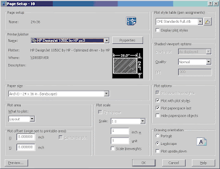
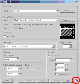
This is where you choose the PC3 file, the CTB file, the page size, plot area, scale, etc. Note that for versions prior to 2005, these selections where available under 2 separate tabs. In the 2005 plot dialog box, you may notice that some options, like the ability to select a CTB file are unavailable.
If this is the case, click on the arrow at the bottom right-hand corner of the dialog box to expand it, and show all of the options.
Now that we've completed all the setup, we can plot to our heart's desire.


